The Smith Chart: A Complete Information
Associated Articles: The Smith Chart: A Complete Information
Introduction
On this auspicious event, we’re delighted to delve into the intriguing matter associated to The Smith Chart: A Complete Information. Let’s weave fascinating data and provide contemporary views to the readers.
Desk of Content material
The Smith Chart: A Complete Information

Summary: The Smith Chart, a graphical software developed by Phillip H. Smith, stays a useful asset in radio frequency (RF) engineering. This text supplies a complete overview of the Smith Chart, explaining its building, its use in impedance matching, transmission line evaluation, and different RF purposes. We’ll delve into the underlying concept, sensible purposes, and the benefits it gives over purely analytical strategies. The article concludes with a dialogue of recent software program implementations and the enduring relevance of the Smith Chart within the age of subtle computer-aided design (CAD) instruments.
1. Introduction:
On this planet of radio frequency (RF) engineering, the correct illustration and manipulation of impedance are essential. Impedance, the opposition to the stream of alternating present, is a fancy amount consisting of resistance and reactance. Calculating impedance transformations, notably in transmission line methods, will be advanced and time-consuming utilizing purely algebraic strategies. That is the place the Smith Chart shines. Developed by Phillip H. Smith in 1937, the Smith Chart is a graphical illustration of the advanced impedance aircraft, permitting engineers to visualise and resolve impedance-related issues with outstanding ease and effectivity. Its round format permits for fast identification of impedance values and their transformations alongside transmission strains. This text goals to supply an intensive understanding of the Smith Chart’s rules, purposes, and continued relevance in trendy RF design.
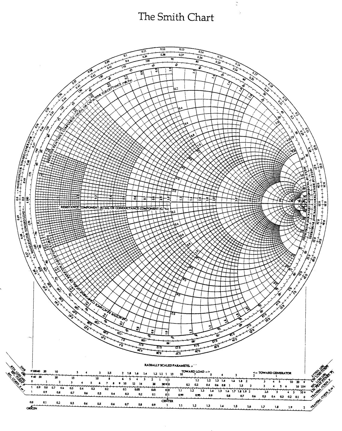
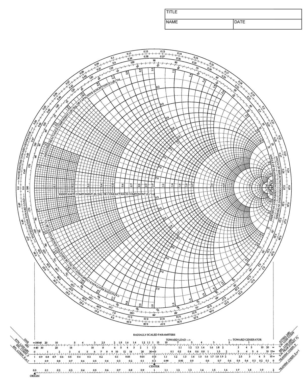
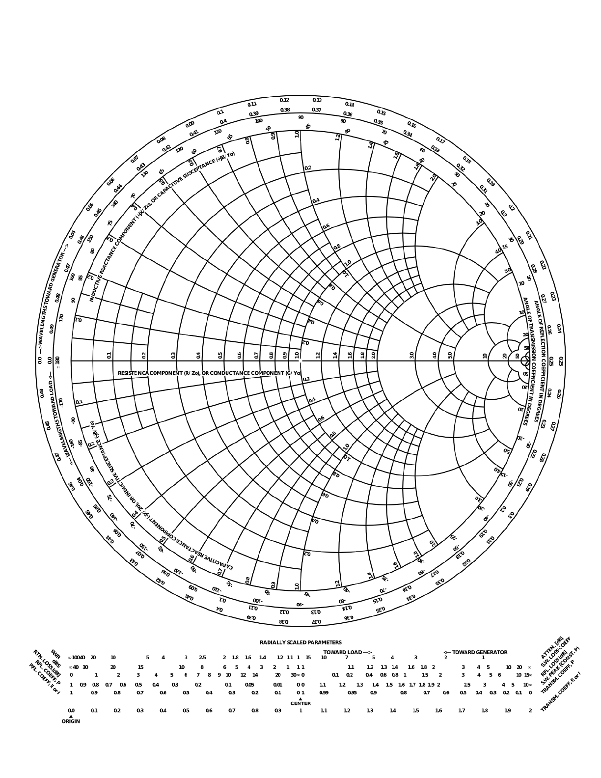
2. Development and Fundamentals:
The Smith Chart relies on the normalized impedance equation:
z = Z/Z₀ = r + jx
the place:
- z is the normalized impedance
- Z is the attribute impedance
- Z₀ is the reference impedance (sometimes 50 ohms)
- r is the normalized resistance
- x is the normalized reactance
The chart maps the advanced impedance aircraft (r, x) onto a round diagram. The fixed resistance circles (circles of fixed r) and fixed reactance circles (circles of fixed x) are households of circles that intersect at proper angles. The middle of the chart represents the normalized impedance z = 1 + j0, which corresponds to an ideal match (no reflection). The periphery of the chart represents infinite impedance and quick circuits.
The Smith Chart additionally incorporates a number of different necessary options:
- Standing Wave Ratio (SWR) Circles: These circles signify fixed values of SWR, a measure of the mismatch between a load impedance and the attribute impedance of the transmission line. A superbly matched system has an SWR of 1.
- Reflection Coefficient (Γ) Illustration: The Smith Chart additionally represents the reflection coefficient, Γ, which is a fancy quantity indicating the amplitude and part of the mirrored wave. The magnitude of Γ is instantly associated to the SWR.
- Wavelength Scale: A wavelength scale across the periphery of the chart permits engineers to find out {the electrical} size of the transmission line wanted to attain a particular impedance transformation.
3. Functions of the Smith Chart:
The Smith Chart’s versatility extends to a variety of RF purposes:
- Impedance Matching: That is arguably the most typical use of the Smith Chart. By plotting the load impedance and utilizing the chart’s options, engineers can rapidly decide the mandatory matching community elements (e.g., inductors and capacitors) to attain an ideal match between the load and the transmission line. This minimizes sign reflections and maximizes energy switch.
- Transmission Line Evaluation: The Smith Chart simplifies the evaluation of transmission strains. By plotting the load impedance and utilizing the wavelength scale, engineers can simply decide the impedance at any level alongside the transmission line. That is essential for understanding sign propagation and figuring out the situation of impedance mismatches.
- Antenna Design: The Smith Chart is used extensively in antenna design to find out the enter impedance of antennas and to design matching networks to optimize antenna efficiency.
- Microwave Circuit Design: The Smith Chart is a vital software in designing and analyzing microwave circuits, notably these involving transmission strains and matching networks.
- Community Evaluation: The Smith Chart can be utilized to investigate advanced networks by systematically combining particular person impedance elements.
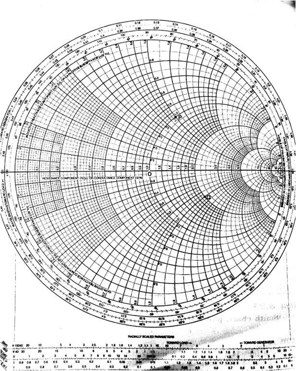
4. Utilizing the Smith Chart for Impedance Matching:
Let’s illustrate the method of impedance matching utilizing a easy instance. Suppose we now have a load impedance of ZL = 75 + j50 ohms and a attribute impedance of Z₀ = 50 ohms. To make use of the Smith Chart:
- Normalize the impedance: z = ZL/Z₀ = (75 + j50)/50 = 1.5 + j1
- Plot the normalized impedance: Find the purpose on the Smith Chart equivalent to r = 1.5 and x = 1.
- Decide the SWR: Draw a circle passing by way of this level and the middle of the Smith Chart. That is the SWR circle. Learn the SWR worth from the circle.
- Design an identical community: The purpose is to maneuver the impedance level alongside the SWR circle in the direction of the middle (z = 1 + j0). This may be achieved by including sequence or shunt elements (inductors or capacitors) at particular factors alongside the transmission line. The Smith Chart helps visualize the impedance transformation attributable to these elements. The size of the transmission line acts as a reactance, shifting the impedance level alongside the SWR circle.
5. Benefits of the Smith Chart:
The Smith Chart gives a number of benefits over purely analytical strategies:
- Graphical Visualization: The Smith Chart supplies a transparent visible illustration of impedance transformations, making it simpler to know advanced relationships.
- Effectivity: The graphical method typically results in faster options in comparison with advanced algebraic calculations.
- Intuitive Understanding: The Smith Chart fosters a deeper intuitive understanding of impedance matching and transmission line habits.
- Error Detection: Graphical strategies may also help determine potential errors in calculations extra simply.
6. Limitations of the Smith Chart:
Regardless of its benefits, the Smith Chart does have some limitations:
- Accuracy: The accuracy of the Smith Chart is restricted by the precision of the graphical illustration.
- Complexity: For extremely advanced networks, the Smith Chart can turn out to be cumbersome to make use of.
- Software program Dependence: Whereas the Smith Chart itself is a graphical software, most trendy purposes make the most of software program implementations, making it reliant on software program availability and performance.
7. Fashionable Implementations and Software program:
Whereas the unique Smith Chart was a hand-drawn software, trendy RF engineers rely closely on software program implementations. Many Digital Design Automation (EDA) software program packages, reminiscent of AWR Microwave Workplace, Keysight ADS, and others, incorporate interactive Smith Charts that present enhanced performance, together with:
- Automated Impedance Matching: Software program can mechanically calculate the values of matching community elements.
- Simulation and Evaluation: The Smith Chart is built-in with simulation instruments, permitting engineers to investigate circuit efficiency beneath varied circumstances.
- Knowledge Import and Export: Software program permits straightforward import and export of information, facilitating collaboration and knowledge administration.
8. Conclusion:
The Smith Chart, regardless of being developed a long time in the past, stays a significant software in RF engineering. Its graphical nature supplies an intuitive and environment friendly method to fixing impedance-related issues. Whereas trendy software program has augmented its capabilities, the underlying rules and the visible illustration proceed to be invaluable for understanding and manipulating impedance in transmission line methods. The Smith Chart’s enduring relevance is a testomony to its elegant design and its skill to bridge the hole between theoretical understanding and sensible software within the subject of radio frequency engineering. Its use will proceed to be important for each skilled RF engineers and people new to the sector, offering a strong and environment friendly technique of analyzing and designing RF circuits and methods. The mixture of the intuitive graphical illustration and the highly effective capabilities of recent software program ensures that the Smith Chart will stay a cornerstone of RF engineering for a few years to come back.


Closure
Thus, we hope this text has offered useful insights into The Smith Chart: A Complete Information. We hope you discover this text informative and useful. See you in our subsequent article!